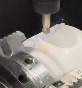
Ensuring dimensional accuracy and positional accuracy when drilling alumina ceramics is a complex process due to the material’s high hardness, brittleness, and susceptibility to cracking. Below is a detailed, step-by-step approach with specific data and strategies to achieve high precision:

1. Selection of Rotary Ultrasonic Machining (RUM) Parameters
Vibration Frequency and Amplitude
- Optimal Frequency: A vibration frequency of 23 kHz has been found effective for drilling alumina ceramics. This frequency enhances material removal rates while minimizing tool wear and thermal damage.
- Amplitude: An amplitude of approximately 20 µm is recommended. This level of vibration improves material removal efficiency without causing excessive stress or cracking.
Spindle Speed
- Optimal Spindle Speed: A spindle speed of 4000 rpm is ideal for drilling alumina ceramics. This speed balances cutting efficiency with precision, reducing the risk of tool deflection and hole inaccuracies.
Feed Rate
- Optimal Feed Rate: A feed rate of 1.5 mm/min is recommended. This rate ensures efficient material removal while maintaining hole quality and minimizing the risk of cracking or chipping.
2. Tool Path Strategies
Mix-2 Tool Path Strategy
- Description: A combination of uni-directional and zigzag tool paths (referred to as Mix-2) has been shown to produce the best results.
- Surface Roughness: This strategy achieves a surface roughness value of Ra = 0.155 µm, which is critical for high-precision applications.
- Dimensional Accuracy: The Mix-2 strategy ensures consistent hole dimensions and positional accuracy.
Spiral or Mix-1 Milling Strategies
- Material Removal Rate (MRR): These strategies maximize MRR, making them suitable for efficient machining without compromising accuracy.
- Application: Ideal for roughing operations where high material removal is required before finishing with Mix-2.
3. Tool Overlapping
Optimal Overlapping Percentage
- Recommended Overlap: A tool overlapping percentage of 20–25% is ideal for achieving smooth surface morphology and high dimensional accuracy.
- Benefits: Higher overlapping reduces surface roughness and ensures uniform material removal, contributing to better hole quality.
4. Monitoring Tool Wear
Types of Tool Wear
- Bond Fracture: Occurs when the bonding material between abrasive particles breaks down, reducing cutting efficiency.
- Rounding of the Tool Edge: Leads to increased cutting forces and reduced precision.
- Plastic Deformation: Causes tool deformation, affecting hole dimensions and positional accuracy.
Monitoring and Maintenance
- Regularly inspect tools for wear using microscopy or other diagnostic techniques.
- Replace tools when wear exceeds acceptable limits to maintain precision.
5. Validation Tests
Post-Drilling Inspection
- Dimensional Tolerances: Use precision measuring tools such as micrometers or coordinate measuring machines (CMMs) to verify hole dimensions.
- Positional Accuracy: Ensure holes are drilled within the specified positional tolerances using CMMs or optical measurement systems.
- Surface Quality: Measure surface roughness using profilometers to confirm compliance with requirements.
6. Additional Strategies for Precision Drilling
Cooling and Lubrication
- Coolants: Use water-based or oil-based coolants to reduce heat generation and prevent thermal stress.
- Lubricants: Apply lubricants to minimize friction and tool wear, ensuring consistent performance.
Workpiece Fixturing
- Precision Fixtures: Secure the workpiece using precision fixtures to minimize vibrations and movement during drilling.
- Soft Jaws: Use soft jaws or cushioning materials to prevent damage to the ceramic surface.
Advanced Techniques
- Ultrasonic-Assisted Drilling: Combines ultrasonic vibrations with conventional drilling to reduce cutting forces and improve precision.
- Laser-Assisted Drilling: Uses laser energy to preheat and soften the material, making it easier to drill with high accuracy.
Summary Table:
Key Strategies and Data for Precision Drilling
| Strategy | Description | Optimal Parameters/Data |
|---|---|---|
| Vibration Frequency | Use ultrasonic vibrations to enhance material removal. | 23 kHz |
| Amplitude | Optimize vibration amplitude for efficient drilling. | 20 µm |
| Spindle Speed | Adjust spindle speed for balanced cutting efficiency. | 4000 rpm |
| Feed Rate | Control feed rate to minimize cracking and chipping. | 1.5 mm/min |
| Tool Path Strategy | Use Mix-2 (uni-directional + zigzag) for best surface finish. | Ra = 0.155 µm |
| Tool Overlapping | Optimize overlapping percentage for smooth surfaces. | 20–25% |
| Cooling & Lubrication | Apply coolants and lubricants to reduce heat and friction. | Water-based or oil-based coolants |
| Tool Wear Monitoring | Regularly inspect and replace worn tools. | Monitor bond fracture, edge rounding, and plastic deformation. |
| Validation Tests | Verify dimensional and positional accuracy using precision tools. | Micrometers, CMMs, profilometers |
By following these detailed strategies and using the provided data, it is possible to achieve high dimensional and positional accuracy when drilling alumina ceramics, ensuring the final product meets stringent quality requirements.